


 ICS Repeater

|
|

The GSM/DCS/PCS Frequency Shift Repeater (FSR) is designed to solve problems of weak mobile signal, which can expand more coverage than RF repeater and reduce investment for the areas where fiber optic or dedicated cable is not allowed.
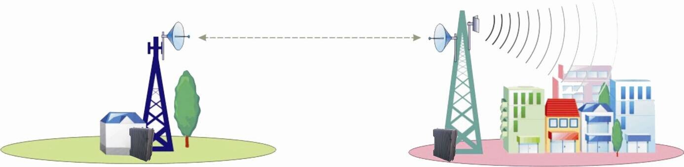
The system consists of two parts: Donor Unit and Remote Unit. The Donor Unit receives the BTS (Base Transceiver Station) signal via open air RF transmission or direct coupler closed to BTS, then converts it from the working frequency to the link frequency, and transmits the amplified signal to the Remote Unit that will reconvert the signal to the working frequency and provide the signal to the areas where network coverage is inadequate. And the mobile signal is also amplified and retransmitted to the BTS via the opposite direction.
As per operator’s requirement for link frequency, two types of FSR are available:
In-Band FSR: the link frequency is inside the working band
Out-of-Band FSR: the link frequency is out of the working band
Features
Application
Specifications
Features
- Aluminum-alloy casing with IP65 protection has high resistance to dust, water and corroding
- No interference to BTS by adopting linear amplifier with high gain and low noise
- Adopting filter with highly selectivity and low insertion loss eliminates interference between uplink and downlink
- USB port provides a link to a notebook for local supervision or to the built-in wireless modem to communicate with the NMS (Network Management System) that can remotely supervise repeater’s working status and download operational parameters to the repeater
Application
- To expand signal coverage or fill signal blind area where signal is weak or unavailable.
- Outdoor: Airports, tourism regions, golf courses, tunnels, factories, mining districts, villages, …
- Indoor: Hotels, exhibition centers, basements, shopping malls, offices, parking lots, …
Technical specifictions
|
Item |
Donor Unit |
Remote Unit |
|||||
|
GSM850/GSM900/DCS1800/PCS1900 |
|||||||
|
Working Frequency (Customized) |
Uplink |
824~849 MHz/880~915 MHz/1710~1785MHz/1850~1910MHz |
|||||
|
Downlink |
|||||||
|
Link Frequency (customized) |
Customized |
||||||
|
Max. Input Power (Non-Destructive) |
10dBm |
||||||
|
Transmission Distance |
≤ 20km |
||||||
|
No. of Channels (for channel shift) |
1 / 2/4 |
||||||
|
Frequency Error |
≤ 0.05ppm |
||||||
|
Phase Distortion across bandwidth |
≤ 6.1° (RMS) & ≤ 24.5° (Peak) |
||||||
|
Error Vector Magnitude (EVM) |
≤ 12.5% |
||||||
|
Maximum Output Power(Customized) |
Uplink |
Wireless access |
≥ 30dBm |
≥ 33dBm |
|||
|
Cable access |
≥ 0dBm |
||||||
|
Downlink |
40dBm |
43dBm |
|||||
|
Maximum Gain |
Wireless access |
≥ 85dB |
≥ 90dB |
||||
|
Cable access |
≥ 45dB |
||||||
|
Gain Adjustment Range |
1~31 dB @ step of 1 dB |
||||||
|
Voltage Standing Wave Ratio |
|||||||
|
Noise Figure |
≤ 5dB(only for uplink) |
||||||
|
Spurious Emission |
Within working band |
≤ -15dBm/30kHz |
|||||
|
Out of working band (∆f > 2.5MHz) |
9kHz~1GHz: ≤ -36dBm/30kHz |
||||||
|
1GHz~12.75GHz: ≤ -30dBm/30kHz |
|||||||
|
Third-order Inter-modulation |
≤ -45dBc / 30kHz (measured under rated output power) |
||||||
|
In-band Ripple |
≤ 3dB |
||||||
|
System Delay |
≤ 10μSec |
||||||
|
I/O Impedance |
50Ω |
||||||
|
RF Connector |
N-Type (Female) / Changeable / bottom of casing |
||||||
|
Temperature Range |
Operation:-25°C~ +55°C/ Storage:-30°C~ +60°C |
||||||
|
Relative Humidity Range |
≤ 95% (non condensing) |
||||||
|
Power Supply (customized) |
DC-48V or AC110V or AC220V,50/60Hz |
||||||
|
Power consumption |
≤ 160W |
≤ 200W |
|||||
|
Backup Power Supply (optional) |
4 hours |
||||||
|
Casing Level |
IP65 |
||||||
|
Dimensions |
428*328*220mm |
||||||
|
Weight |
25kg |
30kg |
|||||
|
NMS Monitoring Function (optional) |
Real-time alarm for door status, temperature, power supply, LNA, VSWR, self-oscillation, etc; Remote control such as turn on/off, increasing/decreasing output power, changing channel frequency, etc; Real-time status for output/input power, UL/DL gain, all status of repeater etc. |
||||||