


 TETRA BDA

|
|

The TETRA Frequency Shift BDA (Bi-directional Amplifier) is designed to solve problems of weak mobile signal, which can expand more coverage than RF BDA and reduce investment for the areas where fiber optic or dedicated cable is not allowed.
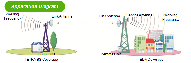
The system consists of two parts: Donor Unit and Remote Unit. The Donor Unit receives the BS (Base Station) signal via open air RF transmission or direct coupler closed to BS, then converts it from the working frequency to the link frequency, and transmits the amplified signal to the Remote Unit that will reconvert the signal to the working frequency and provide the signal to the areas where network coverage is inadequate. And the mobile signal is also amplified and retransmitted to the BS via the opposite direction.
As per operator’s requirement for link frequency, two types of FSR are available:
-
In-Band FS BDA: the link frequency is inside the working band
-
Out-of-Band FS BDA: the link frequency is out of the working band
Features
Application
Specifications
Features
- Aluminum-alloy casing with IP65 protection has high resistance to dust, water and corroding
- Best solution to eliminate mutual interference due to sharing the same frequency
- No stringent isolation requirement for antenna installation
- Easy to choose installation site
- USB port provides a link to a notebook for local supervision or to the built-in wireless modem to communicate with the NMS (Network Management System) that can remotely supervise BDA’s working status and download operational parameters to the BDA
Application
-
To expand signal coverage or enhance signal blind area where TETRA signal is weak or unavailable.
-
Public Safety
-
Transportation
-
Utilities
-
Government
-
Military
-
PAMR
-
Commercial & Industry
-
Oil & Gas
Technical specifictions
|
Model |
AT7K40G |
AT7J43G |
|||||||
|
BDA |
Donor Unit |
Remote Unit |
|||||||
|
Working Frequency |
Uplink |
380~400 MHz (customized) |
|||||||
|
Downlink |
410~430MHz (customized) |
||||||||
|
Link Frequency (customized) |
380~400/410~430MHz |
||||||||
|
Max. Input Power (Non-Destructive) |
10dBm |
||||||||
|
Transmission Distance |
≤ 20km |
||||||||
|
No. of Channels (for channel shift) |
4 Channels |
||||||||
|
Frequency Error |
≤ 0.05ppm |
||||||||
|
Output Power |
Uplink |
Cable access |
≥ 0dBm |
≥ 33dBm |
|||||
|
Downlink |
40dBm (10W) |
43dBm (20W) |
|||||||
|
Gain |
Cable access |
≥ 45dB |
≥ 90dB |
||||||
|
Gain Adjustment Range |
1~31 dB @ step of 1 dB |
||||||||
|
Voltage Standing Wave Ratio |
|||||||||
|
Noise Figure |
≤ 5dB(only for uplink) |
||||||||
|
Spurious Emission |
Within working band |
≤ -15dBm/30kHz |
|||||||
|
Out of working band (∆f > 2.5MHz) |
9kHz~1GHz: ≤ -36dBm/30kHz |
||||||||
|
1GHz~12.75GHz: ≤ -30dBm/30kHz |
|||||||||
|
≤ -45dBc / 30kHz (measured under rated output power) |
|||||||||
|
In-band Ripple |
≤ 3dB |
||||||||
|
System Delay |
≤ 10μSec |
||||||||
|
I/O Impedance |
50Ω |
||||||||
|
RF Connector |
N-Type (Female) / Changeable / bottom of casing |
||||||||
|
Temperature Range |
Operation:-25°C~ +55°C/ Storage:-30°C~ +60°C |
||||||||
|
Relative Humidity Range |
≤ 95% (non condensing) |
||||||||
|
Power Supply (customized) |
AC 220V±15%, 50Hz |
||||||||
|
Power consumption |
≤ 200W |
≤ 220W |
|||||||
|
Backup Power Supply (optional) |
4 hours |
||||||||
|
Casing Level |
IP65 |
||||||||
|
Dimensions |
690mm X420mmX260mm |
||||||||
|
Weight |
33kg |
35kg |
|||||||
|
NMS Monitoring Function |
Real-time alarm for door status, temperature, power supply, LNA, VSWR, self-oscillation, etc; Remote control such as turn on/off, increasing/decreasing output power, changing channel frequency, etc; Real-time status for output/input power, UL/DL gain, all status of BDA , etc. |
||||||||