


 TETRA BDA

|
|
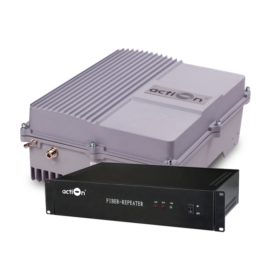

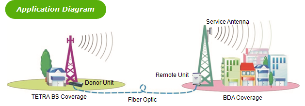
The TETRA Fiber Optic BDA (Bi-directional Amplifier) is designed to solve problems of weak mobile signal in the place that is far away from the Base Station (BS) and has fiber optic cable network underground.
The system consists of two parts: Donor Unit and Remote Unit. The Donor unit captures the BS signal via direct coupler closed to BS, then converts it into optic signal and transmits the amplified signal to the Remote Unit via fiber optic cable. The Remote unit will reconvert the optic signal into RF signal and provide the signal to the areas where network coverage is inadequate. And the mobile signal is also amplified and retransmitted to the BS via the opposite direction.
Features
Application
Specifications
Features
- Aluminum-alloy casing with IP65 protection has high resistance to dust, water and corroding
- Omni-directional antenna can be adopted to expand more coverage
- Tx/Rx control and alarm messages can be transmitted via one fiber optic cable
- Adopting WDM module to realize long-distance transmission
- Stable and improved signal transmission quality
- One Donor Unit can support up to 4 Remote Units to maximize utilization of fiber optic cable
- USB port provides a link to a notebook for local supervision or to the built-in wireless modem to communicate with the NMS (Network Management System) that can remotely supervise BDA’s working status and download operational parameters to the BDA
Application
-
To expand signal coverage or enhance signal blind area where TETRA signal is weak or unavailable.
-
Public Safety
-
Transportation
-
Utilities
-
Government
-
Military
-
PAMR
-
Commercial & Industry
-
Oil & Gas
Technical specifictions
|
Model |
AT7C00A |
AT7B43A |
|||||
|
BDA |
Donor Unit |
Remote Unit |
|||||
|
Working Frequency |
Uplink |
380~400 MHz (Customized) |
|||||
|
Downlink |
410~430MHz (Customized) |
||||||
|
Maximum Input Power (Non-Destructive) |
10 dBm |
||||||
|
Transmission Distance |
≤ 20km |
||||||
|
Output Power |
40dBm / 43dBm |
||||||
|
Gain |
Cable access |
≥ 65dB |
|||||
|
Gain AdjustmentRange |
1~31 dB @ step of 1 dB |
||||||
|
Voltage Standing Wave Ratio |
|||||||
|
Noise Figure |
≤ 5dB(only for uplink) |
||||||
|
In-band Ripple |
≤ 3dB |
||||||
|
Spurious Emission |
Within working band |
≤ -15dBm/30kHz |
|||||
|
Out of working band (∆f > 2.5MHz) |
9kHz~1GHz: ≤ -36dBm/30kHz |
||||||
|
1GHz~12.75GHz: ≤ -30dBm/30kHz |
|||||||
|
≤ -45dBc / 30kHz (measured under rated output power) |
|||||||
|
System Delay |
≤ 5μSec |
||||||
|
I/O Impedance |
50Ω |
||||||
|
RF Connector |
N-Type (Female) / Changeable / bottom of casing |
||||||
|
Fiber Optic Light Source |
Laser unit (wavelength:1310nm/1550nm) |
||||||
|
Optical Output Power |
≥0dBm(1310nm) / ≥3dBm(1550nm) |
||||||
|
Optical Receiver Sensitivity |
≤-25dBm |
||||||
|
Temperature Range |
Operation:-25°C~ +55°C/ Storage:-30°C~ +60°C |
||||||
|
Relative HumidityRange |
≤ 95% (non condensing) |
||||||
|
Power Supply (customized) |
DC +24V / AC 220V±15% or AC 110V±15%, 50Hz |
||||||
|
Power consumption |
≤ 15W |
≤ 180W |
|||||
|
Backup Power Supply (optional) |
4 hours |
||||||
|
Casing Level |
-- |
IP65 |
|||||
|
Dimensions |
418mm X90mmX290mm |
640mm X 400mm X 230mm |
|||||
|
Weight |
6kg |
35kg |
|||||
|
NMS Monitoring Function |
Real-time alarm for door status, temperature, power supply, LNA, VSWR, self-oscillation, etc; Remote control such as turn on/off, increasing/decreasing output power, c, etc; Real-time status for output/input power, UL/DL gain, all status of BDA, etc. |
||||||