


 TETRA BDA

|
|
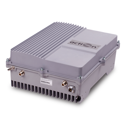

The TETRA ICS Repeater is designed to provide a more cost-effective solution than adding a new Base Transceiver Station (BTS) to improve signal coverage and communication quality in TETRA system. And its easy installation and maintenance can help carriers get fast return.
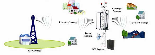
The repeater is working as a relay between the BTS and mobiles. It receives the low-power signal from BTS via the Donor Antenna, linearly amplifies the signal and then retransmits it via the Coverage Antenna to the weak/blind coverage area. And the mobile signal is also amplified and retransmitted to the BTS via the opposite direction
Features
Application
Specifications
Features
- Aluminum-alloy casing with IP65 protection has high resistance to dust, water and corroding
- Highly selective digital channel selector can process 8 channels simultaneously
- Real Time Interference Signal Cancellation (Multi-path Fading, Feed-Back signal)
- Adopting filter with highly selectivity and low insertion loss eliminates interference between uplink and downlink
- USB port provides a link to a notebook for local supervision or to the built-in wireless modem to communicate with the NMS (Network Management System) that can remotely supervise repeater��s working status and download operational parameters to the repeater
Application
To expand signal coverage or enhance signal blind area where TETRA signal is weak or unavailable.
Outdoor: Airports, tourism regions, golf courses, tunnels, factories, mining districts, villages, ��
Technical specifictions
|
Items |
Specifications |
|
|
Working Frequency (Customized) |
Uplink |
380~385 MHz |
|
Downlink |
395~400 MHz |
|
|
Maximum Output power(Customized) |
43dBm |
|
|
Maximum Gain |
100dB |
|
|
Gain Adjustment Range |
1~31 dB @ step of 1 dB |
|
|
Operating Maximum Gain |
�� Antenna Isolation + 10dB |
|
|
No. of Channels |
8 |
|
|
Power Amplifier Oscillation Protection |
Interference Cancellation System |
|
|
Cancellation Feedback Signals �C Maximum Sizes of Window |
�� 6��Sec |
|
|
Interference Cancellation Range |
�� 25dB |
|
|
Frequency Error |
�� 0.05ppm |
|
|
Voltage Standing Wave Ratio |
�� 1.5 |
|
|
Noise Figure |
�� 6dB |
|
|
In-band Ripple |
�� 3dB |
|
|
Maximum Input Power (Non-Destructive) |
-10dBm |
|
|
Spurious Emission |
�� -36dBm |
|
|
Third-order Inter-modulation |
�� -45dBc/30KHz(measured under rated output power) |
|
|
System Delay |
�� 5.0��Sec |
|
|
I/O Impedance |
50�� |
|
|
RF Connector |
N-Type (Female) |
|
|
Temperature Range |
Operation: -25��C~ +55��C/ Storage:-30��C~ +60��C |
|
|
Relative Humidity Range |
�� 95% (non condensing) |
|
|
Environment Class |
IP65 |
|
|
Dimensions |
610mm X445mmX215mm |
|
|
Weight |
�� 35Kg |
|
|
Power Supply (customized) |
||
|
Backup Power Supply (optional) |
4 hours |
|
|
NMS Monitoring Parameters (optional) |
UL/DL Power, UL/DL Max Gain, RSSI, ATT, Channel No, UL/DL Output ALC, Power alarm Threshold, UL/DL PA Temperature etc |
|
|
NMS Controlled Parameters (optional) |
Channel No., ATT, Output Power Thresholds UL/DL, UL/DL Output ALC , PA Switch ,Alarm Report can be enable /disable etc |
|