


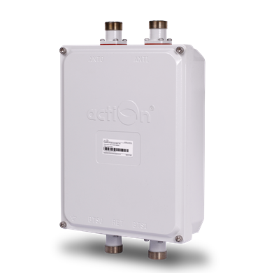
 Combiner

|
|

Schematic Diagram:


Features
Application
Specifications
Features
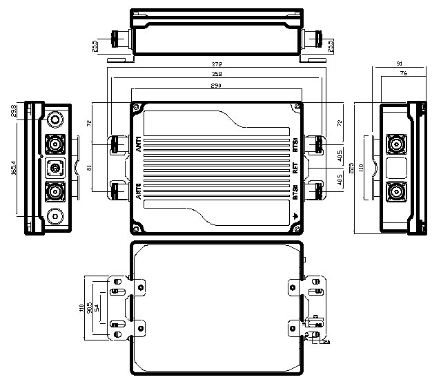
Outline Drawing for Single Unit:
Application
Clamp Set:
Clamp set suitable for mast diameter
of 64-114mm


Technical specifictions
|
Items |
Uplink |
Downlink |
|
|
Working Frequency(customize) |
Band1 |
824~849 MHz |
869~894MHz |
|
Band2 |
890~915 MHz |
935~960MHz |
|
|
Band3 |
1710~1785 MHz |
1805~1880MHz |
|
|
Band4 |
1850~1910 MHz |
1930~1990MHz |
|
|
Gain |
12��1dB |
-- |
|
|
Flatness |
�ܡ�0.5 dB |
-- |
|
|
Noise Figure |
�� 1.8 dB |
-- |
|
|
Group Delay |
45 ns max over any 5MHz in Rx band |
||
|
Return Loss in By Pass Mode |
>15dB |
>18dB |
|
|
Return Loss in Normal Mode |
>17dB |
>18dB |
|
|
Max Input Power |
<12dBm |
-- |
|
|
Insert loss in by-pass mode |
2.8dB max |
0.50dB typ.,0.70dB max |
|
|
Inter-modulation products in RX band |
<-112dBm (2 Tx carriers at +43 dBm) (Power up) |
||
|
Output 1 dB Compression |
-- |
||
|
I/O Impedance |
50�� |
||
|
Power Supply |
DC 10~30 V |
||
|
Operating current per TMA (without RET) |
Nom. 280mA at 10 V Nom. 110 mA at 30V |
||
|
Power Handing |
2.5KWPEAK;200w AVG |
||
|
Alarm management(Optional) |
AISG |
||
|
Material |
Aluminum housing |
||
|
7/16 DIN female |
|||
|
AISG Connector(Optional) |
8-pin female, IEC 60130-9 (Pin 3: RS485B, pin 5: RS485A, pin1&pin 6: 9 �C 30V DC, pin 7: DC return, other pins: not connected) |
||
|
Working Temperature Range |
-40 ~ + 65��C |
||
|
Application |
Indoor or Outdoor(IP67) |
||
|
EMC |
According to ETS 300 342-3 |
||
|
MTBF |
> 1 000 000 hours (per TMA) |
||